
What if the “unexplained” production line failure that cost your facility thousands last week wasn’t a mechanical error at all, but a transient event your current sensors simply failed to catch? For many plant managers, the frustration of sensitive VFDs and PLCs tripping without a clear cause is a recurring nightmare that erodes profitability. It’s often impossible to demand accountability from utility providers when you lack the empirical data to prove a power quality event occurred. You likely already know that even a millisecond of instability can derail a complex automated process, yet pinpointing the exact signature of that disturbance remains elusive.
This technical guide provides the expertise needed to master the architecture and implementation strategies of voltage dip recording systems to eliminate unexplained industrial downtime. By transitioning from reactive maintenance to a systematic monitoring approach, you can achieve uninterrupted production and extend the longevity of your critical infrastructure. We will explore the integration of high-resolution recording hardware, the application of IEC 61000-4-34 standards, and the scientific root-cause analysis required to transform raw electrical data into actionable operational intelligence. Mastering these systems ensures that your facility remains resilient against the volatility of the modern power grid.
Key Takeaways
- Identify the hidden financial risks of voltage sags and learn how to distinguish transient events from total power interruptions.
- Evaluate high-speed sampling and memory buffer requirements when selecting voltage dip recording systems to ensure accurate waveform reconstruction.
- Discover how to integrate monitoring hardware into existing SCADA networks using industry-standard protocols like Modbus TCP and IEC 61850.
- Master root-cause analysis by overlaying disturbance data on SEMI F47 curves to determine if faults originate from the utility or internal equipment.
- Explore strategies for retrofitting advanced power quality recording into legacy switchgear to extend asset life and improve system transparency.
The Engineering Necessity of Voltage Dip Recording Systems
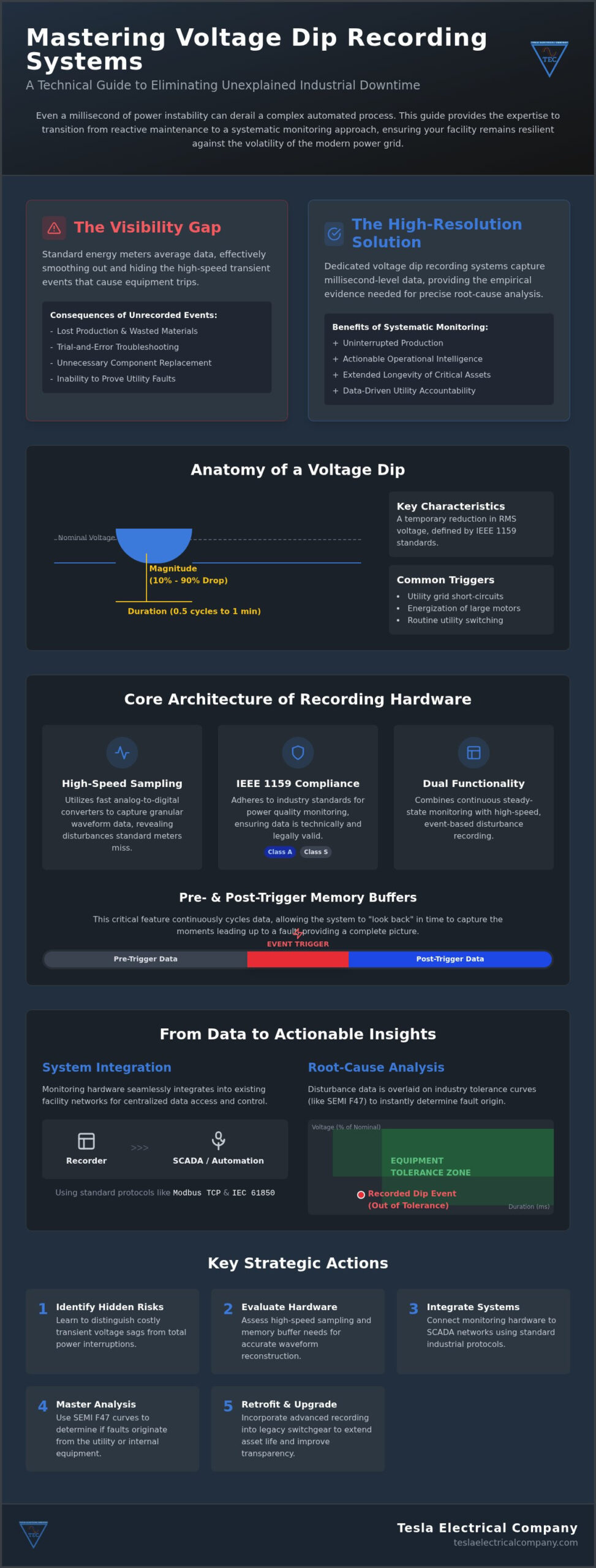
Industrial facilities operate within a landscape where electrical stability is often assumed but rarely verified at the millisecond level. While standard energy meters provide useful data for billing and load profiling, they are fundamentally incapable of capturing the high-speed transients that trigger modern automation failures. These standard devices typically average root-mean-square (RMS) values over multiple cycles, effectively smoothing out the very disturbances that cause a sensitive Variable Frequency Drive (VFD) to trip. Implementing dedicated voltage dip recording systems bridges this visibility gap, providing the high-resolution data required to differentiate between a minor utility fluctuation and a catastrophic equipment fault.
The financial consequences of these unrecorded events are severe. In continuous manufacturing sectors, a single process interruption can result in hours of lost production, wasted raw materials, and complex restart sequences. Without empirical evidence from disturbance recording, engineering teams are forced into trial and error troubleshooting, often replacing healthy components while the root cause remains unaddressed. A Voltage sag (or dip) is not merely a technical nuisance; it’s a significant threat to operational profitability that demands a systematic monitoring solution.
Anatomy of a Voltage Dip: Duration and Magnitude
A voltage dip is characterized by a temporary reduction in the RMS voltage, typically falling between 10% and 90% of the nominal value. These events are often triggered by short-circuit faults on the utility grid, the sudden energization of large inductive loads like industrial motors, or routine utility switching operations. According to IEEE 1159 standards, a voltage dip is defined as a decrease to between 0.1 and 0.9 pu in rms voltage or current at the power frequency for durations of 0.5 cycles to 1 minute. Identifying these specific parameters allows engineers to determine if an event originated upstream in the utility network or downstream within the facility’s own distribution system.
Impact on Sensitive Industrial Equipment
Modern power electronics are highly intolerant of voltage instability. VFDs are particularly vulnerable, as a brief dip can cause the DC bus voltage to drop below the threshold required to maintain motor control, leading to immediate under-voltage trips. Similarly, Programmable Logic Controllers (PLCs) may experience logic resets or communication timeouts that halt entire production lines. Beyond immediate stoppages, frequent transients exert cumulative thermal and electrical stress on motor insulation, shortening the lifespan of expensive assets. Integrating voltage dip recording systems into your infrastructure allows for a proactive switchgear condition assessment, ensuring that protection settings are optimized to ride through minor disturbances while isolating genuine faults.
Technical Architecture of Modern Recording Hardware
The efficacy of voltage dip recording systems depends entirely on the fidelity of the captured waveform. Unlike standard power meters that aggregate data over several cycles, modern recording hardware utilizes high-speed analog-to-digital converters to provide granular visibility into transient events. To ensure that recorded data is technically and legally valid for utility disputes, hardware must adhere to the IEEE 1159 Standard for monitoring power quality. This classification distinguishes between Class A devices, which provide high-precision measurements for contractual verification, and Class S devices, which are intended for internal troubleshooting and statistical analysis.
Modern systems offer dual-functionality by combining continuous steady-state monitoring with event-based disturbance recording. A critical feature of this architecture is the implementation of pre-trigger and post-trigger memory buffers. These buffers continuously cycle data through the device’s RAM, allowing the system to “look back” in time once a threshold is breached. This ensures that the milliseconds of electrical instability leading up to a trip are preserved, providing a complete picture of the fault’s inception rather than just its conclusion.
Transducer and Sensor Integration
The measurement chain begins with high-accuracy Current Transformers (CTs) and Potential Transformers (PTs). Selecting transducers with low phase shift and minimal signal distortion is vital for maintaining the integrity of the recording. For retrofit applications where space is limited or downtime must be minimized, Rogowski coils serve as an excellent alternative for current measurement. These flexible sensors don’t suffer from magnetic saturation, making them ideal for capturing the high-magnitude currents often associated with the faults that trigger voltage dips. Ensuring these sensors are correctly matched to the recording hardware is a service often provided by a specialized power quality partner to guarantee system accuracy.
Data Storage and Edge Processing
As sampling rates increase, the volume of generated data necessitates sophisticated edge processing capabilities. High-resolution event logs require significant on-board storage to prevent data loss during network outages. A 256-samples-per-cycle rate is the industrial baseline because it provides sufficient resolution to accurately reconstruct the waveform up to the 50th harmonic while capturing sub-cycle transients. Edge computing allows the device to perform real-time harmonic analysis and dip classification locally. This reduces the bandwidth required for SCADA transmission by only sending processed alerts and relevant waveform captures to the central control room, rather than a continuous stream of raw data.
Integrating Recording Systems into SCADA and Automation
Capturing high-resolution data is only the first stage of effective power quality management. To derive operational value, voltage dip recording systems must be seamlessly integrated into the facility’s broader control network. This connectivity allows for real-time visualization and automated responses to electrical disturbances. Modern industrial environments rely on standardized communication protocols to ensure interoperability between monitoring hardware and centralized controllers. While Modbus TCP remains a common baseline for basic data exchange, many sophisticated facilities utilize IEC 61850 for its high-speed peer-to-peer messaging capabilities, or MQTT for efficient data transmission to cloud-based analytics platforms.
Precise event correlation across a distributed network requires sub-millisecond synchronization. When a disturbance occurs, engineers must be able to align the timestamp of a recorded waveform with the exact millisecond a PLC reported a process trip. Utilizing Precision Time Protocol (PTP) or GPS-based clock synchronization ensures that every device on the network operates on a unified timeline. This level of accuracy is essential for determining the sequence of events and identifying whether a fault propagated from the utility or was generated internally by large motor starts.
Unified Monitoring Architecture
Effective oversight requires consolidating power quality data from multiple MV and LV switchboards into a single pane of glass. By embedding these insights within SCADA and automation system solutions, operators can view electrical health alongside process parameters. This unified approach enables the automation of load shedding or backup sequences based on pre-defined dip thresholds. For instance, if a system detects a voltage sag exceeding a specific magnitude and duration, it can trigger an immediate transfer to a secondary source or initiate a controlled shutdown of non-critical loads to preserve the stability of sensitive production lines.
Redundancy in Monitoring Systems
A monitoring system is only as reliable as its ability to operate during a power failure. Ensuring recording continuity during a total loss of supply requires a robust power backup strategy for the recording hardware and its associated communication infrastructure. Applying a redundant control system architecture to the monitoring network prevents single points of failure from blinding the facility during critical events. Fail-safe data logging ensures that even if the primary network connection is lost, the event waveforms are stored locally and synchronized once connectivity is restored, preventing the loss of vital diagnostic data.
Analysing Recorded Data for Root-Cause Identification
Capturing high-resolution waveforms is a prerequisite for stability, but the ultimate utility of voltage dip recording systems depends on the rigor of the subsequent analysis. Engineering teams must move beyond simply identifying that an event occurred to understanding its specific impact on the facility’s electrical ecosystem. This is achieved by overlaying disturbance data on standardized susceptibility curves, such as the ITIC (CBEMA) or SEMI F47, which provide a graphical representation of equipment tolerance levels. These curves help determine if a dip fell within the “safe” zone or if it was severe enough to justify an immediate equipment trip.
Distinguishing between upstream utility faults and downstream facility disturbances is the primary objective of root-cause identification. By comparing the phase relationship and current magnitude during a dip, engineers can determine if the event was pulled into the facility by an external short circuit or pushed out by a large internal motor start. Proficiency in interpreting power quality analysis reports is essential for this differentiation, allowing managers to hold utility providers accountable or focus internal maintenance efforts where they are most needed. Correlating these electrical disturbances with specific production line failures transforms raw data into a roadmap for industrial electrical system reliability and long-term system optimization.
Waveform Analysis Techniques
Modern waveform analysis allows for the identification of harmonic signatures produced by non-linear loads, such as large rectifiers or VFDs. Spotting transient precursors, such as brief voltage spikes or high-frequency ringing, can often predict equipment failure before a catastrophic trip occurs. The SEMI F47 curve is specifically significant in semiconductor manufacturing because it establishes the mandatory voltage sag immunity levels for sensitive processing equipment, ensuring production continuity during standard grid fluctuations. These detailed forensic techniques ensure that no disturbance remains “unexplained.”
Utility Accountability and Grid Compliance
Maintaining precise, time-stamped records is the only way to challenge utility service level agreements with technical authority. If the data reveals chronic grid instability, it provides the empirical justification required for investments in capacitor banks or specialized protection relays. In the event of a commercial dispute regarding equipment damage, Class A certified recording data carries significant legal weight, serving as an objective “black box” for the facility’s power supply. For organizations requiring total transparency, implementing a comprehensive Power Quality and Disturbance Recording System is the definitive strategy for mitigating electrical risk.
Engineering Bespoke Recording and Retrofit Solutions
Implementing high-performance voltage dip recording systems requires more than just high-speed sensors; it demands a deep understanding of the physical environment where these electronics operate. For new installations, the integration of recording modules is handled at the foundational level of industrial switchboard design. This ensures that thermal management, electromagnetic interference (EMI) shielding, and communication cabling are optimized from the outset. However, the most significant challenge for many facility managers lies in integrating these advanced capabilities into existing, aging infrastructure where space and compatibility are often limited.
A successful deployment starts with a strategic switchgear condition assessment. This technical evaluation determines if the current busbar configuration, protection relay logic, and instrument transformer accuracy can support high-fidelity disturbance recording. By identifying these variables early, engineers can design bespoke panels that house the recording hardware separately or integrate it directly into existing cubicles without compromising the mechanical integrity of the switchgear. This lifecycle support approach ensures that the monitoring system remains a permanent, serviceable asset rather than a temporary fix.
Retrofitting Legacy Industrial Infrastructure
Retrofitting modern recording systems into legacy switchgear often reveals compatibility gaps between analog protection and digital monitoring. Upgrading protection relays to newer models with integrated disturbance logging is a common strategy to modernize the facility while adding visibility. To minimize production downtime, these installations are typically planned during scheduled maintenance windows, utilizing pre-wired sub-assemblies that fit into existing switchgear slots. This methodical approach ensures that the facility gains “black box” diagnostic capabilities with minimal disruption to the manufacturing process.
The Tesla Electrical Company Approach
Tesla Electrical Company provides a total solution that spans from initial engineering design to final execution and long-term maintenance. Our expertise in redundant systems ensures that your monitoring network remains operational even during the most severe grid disturbances. We provide end-to-end integration across LV/MV switchboards and SCADA networks, bridging the gap between electrical hardware and process control software. Our commitment extends to ongoing technical support and spare parts availability, ensuring that your voltage dip recording systems remain a reliable pillar of your facility’s industrial electrical system reliability strategy for decades. We prioritize the stability of your operations by delivering engineering excellence that matches the specialized language of your industry.
Securing Industrial Continuity Through Power Quality Intelligence
Mastering the technical nuances of power quality is no longer optional for high-stakes manufacturing environments. You have seen how high-speed sampling and memory buffers provide the transparency needed to diagnose transient events that standard meters simply ignore. By integrating these insights into your SCADA network, you transform raw electrical data into a strategic asset that prevents unexplained production stoppages. This level of oversight is the foundation of a resilient, modern facility.
Implementing voltage dip recording systems represents a commitment to scientific root-cause analysis and long-term equipment longevity. Whether you are designing a new facility or retrofitting legacy switchgear, the goal remains the same: total visibility over your electrical infrastructure. Tesla Electrical Company has been dedicated to industrial infrastructure excellence since 2015, specializing in LV/MV switchboards and the complex retrofit of circuit breakers and protection relays. Our team provides the authoritative expertise required to bridge the gap between electrical hardware and process continuity.
Consult with Tesla Electrical Company for a custom Power Quality Recording solution to ensure your facility operates with the reliability that modern industry demands. Achieving a resilient power profile is a methodical process; with the right engineering partner, it’s entirely within reach.
Frequently Asked Questions
What is the primary difference between a power meter and a voltage dip recording system?
A power meter typically measures steady-state parameters like voltage, current, and energy consumption by averaging values over multiple cycles. In contrast, voltage dip recording systems are designed to capture high-speed transients and sub-cycle disturbances that standard meters miss. These systems utilize high-resolution sampling and memory buffers to reconstruct the exact waveform of an event. This allows engineers to see the precise inception and duration of a fault rather than just a multi-cycle average.
How does a voltage dip recording system help in reducing industrial downtime?
These systems reduce downtime by providing the empirical data needed for scientific root-cause analysis. Instead of guessing why a VFD or PLC tripped, maintenance teams can review the recorded waveform to identify the specific trigger. This eliminates the costly trial and error approach to troubleshooting and prevents unnecessary equipment replacement. By identifying whether a disturbance is recurring, facilities can implement proactive mitigation strategies like capacitor banks or UPS systems before a catastrophic failure occurs.
Can voltage dip recording systems be retrofitted into existing MV switchboards?
Yes, modern monitoring hardware is frequently retrofitted into existing MV and LV switchboards to enhance system transparency. Tesla Electrical Company specializes in the retrofit of circuit breakers and protection relays, which often serves as the ideal entry point for adding disturbance recording capabilities. Depending on space constraints, we utilize flexible Rogowski coils or specialized instrument transformers to integrate these modules without requiring extensive structural modifications to your legacy industrial infrastructure.
What sampling rate is required for a system to be considered high-resolution?
For a system to be considered high-resolution in an industrial context, a sampling rate of at least 256 samples per cycle is generally required. This rate allows for the accurate reconstruction of waveforms up to the 50th harmonic and captures transient events lasting only a fraction of a millisecond. While some basic monitors offer lower rates, high-performance voltage dip recording systems ensure that the complex signatures of high-frequency disturbances are preserved for detailed forensic engineering analysis.
How does ITIC/CBEMA curve analysis assist in evaluating equipment trips?
ITIC and CBEMA curves provide a standardized benchmark for evaluating the sensitivity of electronic equipment to voltage variations. By overlaying recorded dip data onto these curves, engineers can immediately determine if a specific event fell outside the equipment’s design tolerance. This analysis is critical for identifying marginal equipment that trips during minor fluctuations. It allows for more precise adjustments to protection settings or the targeted installation of voltage stabilization hardware where equipment is most vulnerable.
Is it necessary to integrate voltage dip recorders with the facility SCADA system?
Integration with a SCADA system is essential for achieving facility-wide visibility and automated disturbance response. While standalone recorders log data locally, SCADA integration allows operators to correlate electrical events with process failures in real-time. This connectivity supports automated logic, such as load shedding or backup sequences, based on pre-defined dip thresholds. It ensures that critical data is synchronized across the entire automation network, providing a unified platform for both electrical monitoring and process control.
What are the benefits of using Class A certified recording equipment?
Class A certification, as defined by IEC 61000-4-30, ensures that the recording equipment utilizes standardized measurement methods that are technically and legally valid. This certification is vital when challenging utility providers over service level agreement violations or in commercial disputes involving equipment damage. Using Class A hardware guarantees that measurements are consistent regardless of the manufacturer, providing a level of accuracy and reliability that is required for contractual verification and high-stakes engineering decisions.
How do recording systems distinguish between internal facility faults and utility grid issues?
Recording systems distinguish between internal and external faults by analyzing the relationship between voltage and current at the point of common coupling. An upstream utility fault typically shows a voltage drop accompanied by a decrease in current flowing into the facility. Conversely, an internal fault generated by a large motor start or a downstream short circuit usually results in a voltage dip paired with a significant current surge. This directional analysis is fundamental for establishing utility accountability.
Disclaimer
Some content, images, text, or other materials on this website may have been created or assisted by artificial intelligence (AI).
While we review AI-generated content for accuracy and quality, we do not guarantee that all information is free from errors or omissions.
Content generated using AI is provided for informational purposes only and should not be solely relied upon without independent verification.