
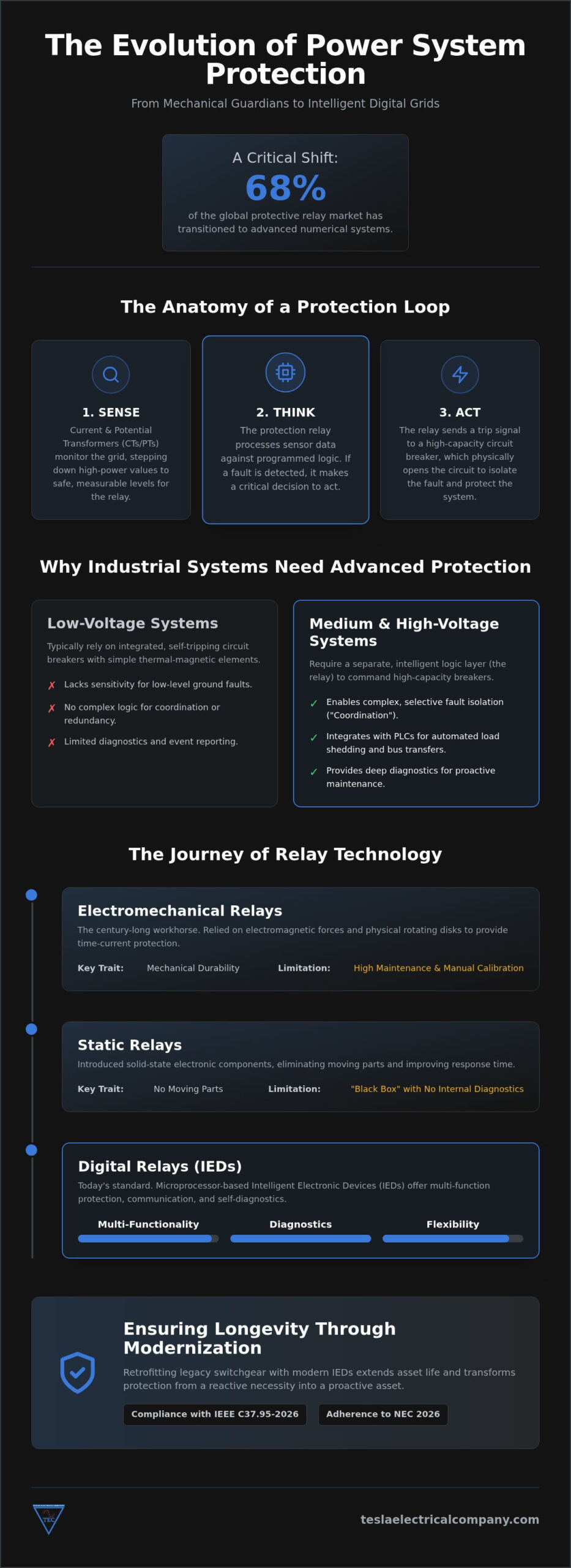
While digital transformation dominates industrial discourse, the silent reality is that 68% of the global protective relay market has transitioned to numerical systems to combat the volatility of modern grids. You likely recognize the mounting pressure of maintaining aging infrastructure where nuisance tripping and legacy switchgear integration create persistent operational friction. Relying on outdated power system protection relays doesn’t just invite minor downtime. It risks catastrophic equipment failure that can derail an entire enterprise. We understand that the gravity of these high-stakes requirements demands more than a temporary fix; it requires a systematic commitment to technical excellence and grid stability.
This comprehensive reference ensures you master the technical fundamentals and strategic applications of protection relays to secure industrial system resilience and longevity. You’ll gain a clear understanding of modern relay classifications and a methodical framework for selecting specific protection functions tailored to complex environments. We also explore how to extend asset life through precise retrofitting, aligning your infrastructure with the rigorous IEEE C37.95-2026 standards and the latest NEC 2026 requirements. By the end of this guide, you’ll possess the professional oversight needed to transform your protection strategy from a reactive necessity into a proactive asset.
Key Takeaways
- Distinguish between simple low-voltage circuit breakers and the sophisticated decision-making logic required for medium and high-voltage infrastructure.
- Trace the evolution of protection technology to understand why modern Intelligent Electronic Devices (IEDs) offer superior reliability over legacy mechanical relays.
- Master the application of ANSI standard codes to properly configure power system protection relays for overcurrent, differential, and distance protection.
- Identify specific protection requirements for critical industrial assets, including generator synchronizing control panels and medium-voltage feeders.
- Implement a methodical framework for retrofitting legacy switchboards to extend asset life and ensure compliance with the latest 2026 electrical standards.
The Role of Protection Relays in Industrial Infrastructure
Industrial electrical grids function as the lifeblood of modern production; however, their complexity necessitates a sophisticated layer of oversight. Within these environments, power system protection relays serve as the primary decision-making components. While low-voltage systems often rely on self-tripping circuit breakers with integrated thermal-magnetic elements, medium and high-voltage systems require a separate, intelligent logic layer. These relays don’t carry the primary load current themselves. Instead, they monitor system parameters and command high-capacity circuit breakers to act only when specific, pre-defined fault conditions occur.
The implementation of a Protective relay strategy focuses on three critical objectives: personnel safety, equipment preservation, and system stability. Achieving these goals requires precise “Selectivity” and “Coordination.” Selectivity ensures that a fault in one branch doesn’t cause a total facility blackout. By coordinating the time-current characteristics of multiple relays, engineers can isolate the smallest possible section of the grid, maintaining power to mission-critical processes elsewhere.
Why Industrial Systems Require External Protection Logic
Standard thermal-magnetic sensing has significant limitations in high-capacity industrial environments. It lacks the sensitivity to detect low-level ground faults or the sophistication to handle bidirectional power flows. External relays allow for complex logic, such as directional sensing and programmable logic controllers (PLC) integration. This capability is vital when engineering a redundant control system architecture. In such setups, relays communicate with each other to manage load shedding or automated bus transfers, ensuring that industrial resilience is maintained even during localized component failures.
The Core Components of a Protection Loop
A functional protection loop consists of three distinct stages that work in a continuous cycle of monitoring and response. First, Current Transformers (CTs) and Potential Transformers (PTs) act as sensors, stepping down high voltages and currents to safe, measurable levels. Second, the relay unit processes this data against its programmed logic. If the input exceeds the set “pickup” value, the relay initiates a trip signal. Finally, the circuit breaker’s trip coil receives this electrical pulse, physically opening the contacts to clear the fault. This systematic separation of sensing, thinking, and acting is what allows power system protection relays to manage the immense energies found in heavy industrial infrastructure.
Classification of Relays: From Electromechanical to Digital
The transition from mechanical to digital architecture marks a fundamental shift in how industrial facilities manage electrical risk. Early power system protection relays utilized induction disk mechanisms, where physical rotation provided the necessary time-current characteristics. While these devices established a legacy of reliability, they demanded rigorous maintenance schedules and manual calibration. Static relays eventually introduced solid-state components to eliminate moving parts, yet they still lacked the comprehensive diagnostic capabilities required by modern high-stakes environments.
Electromechanical and Static Relays
Electromechanical relays were the primary solution for industrial plants for nearly a century. Their operation relies on electromagnetic forces acting on a movable armature or disk. While remarkably durable, their limitations became apparent as systems grew more complex. Static relays mitigated some issues by utilizing electronic circuitry to perform the measuring and timing functions. However, both technologies remain “black boxes” that offer no real-time data regarding their internal health or the specific nature of the faults they clear.
Microprocessor-Based Digital Relays
Today, microprocessor-based digital relays, often categorized as Intelligent Electronic Devices (IEDs), define the standard for industrial resilience. These units provide multi-functionality that previously required an entire panel of individual components. They offer integrated self-monitoring, which alerts operators to internal circuit failures before a fault occurs. This shift is reflected in the market data; digital and numerical relays represented 68.0% of the protective relay market in 2025, a figure that continues to rise as facilities prioritize data-driven oversight.
One of the most profound benefits of modern digital relays is their role in SCADA and automation system solutions. By utilizing standardized communication protocols like IEC 61850, these relays transform from isolated safety devices into active data nodes. They provide granular insights into power quality and disturbance recording, allowing for precise post-fault analysis. Additionally, the implementation of Adaptive Protective Relay Settings allows these systems to dynamically adjust protection parameters, which is essential for managing the bidirectional power flows associated with onsite renewable integration. If your infrastructure still depends on legacy mechanical hardware, it’s worth considering how a targeted protection relay upgrade can enhance your system’s intelligence and reliability.
Primary Protection Functions and ANSI Standard Codes
Precision in industrial protection relies on a standardized language of function numbers established by ANSI and IEEE. These codes allow engineers to specify exactly how power system protection relays should respond to various electrical anomalies. Utilizing high-accuracy hardware from industry leaders, such as SEL protection relays and Basler protection relays, ensures that sensing remains within strict tolerances. This accuracy is paramount when configuring “Selectivity” logic, a methodical approach that ensures only the circuit breaker closest to the fault opens, thereby preventing unnecessary upstream outages.
Effective system design requires a deep understanding of Power System Protective Relaying concepts to map these codes to physical hardware. By categorizing relays according to their ANSI function numbers, facility managers can establish a rigorous defense against overloads, short circuits, and internal equipment failures. This structured oversight is the foundation of industrial electrical resilience.
Overcurrent and Ground Fault Protection (50/51/50N/51N)
Overcurrent protection is the most fundamental layer of an industrial safety scheme. Instantaneous overcurrent (50) provides an immediate trip when current exceeds a high threshold, typically during a direct short circuit. In contrast, time-delay overcurrent (51) allows for temporary, safe surges, such as motor starting currents, before initiating a trip. Ground fault protection (50N/51N) specifically monitors the neutral or zero-sequence current to detect leakage to earth, which prevents catastrophic insulation failure and reduces fire risks. The Inverse Definite Minimum Time (IDMT) curve serves as the global standard for coordination, ensuring that trip times decrease as the fault severity increases.
Differential and Distance Protection (87/21)
For high-value assets like large power transformers and motors, Differential (87) protection offers the highest level of sensitivity. It functions by comparing the current entering a device with the current leaving it; any discrepancy indicates an internal fault, triggering an instantaneous shutdown. Distance (21) protection is primarily applied to industrial transmission lines and long feeders. It calculates the impedance of the line to determine if a fault has occurred within a specific “zone” of the infrastructure. These sophisticated functions are vital when engineering critical power redundant systems for industrial resilience, as they allow for the rapid, automated isolation of faulted segments without compromising the entire redundant network.
Critical Application Areas in Industrial Power Distribution
The strategic deployment of power system protection relays must align with the specific electrical topographies found in heavy infrastructure. Generic protection schemes often fail to account for the unique stresses of industrial loads, such as high-inertia motor starts or the complexities of onsite power generation. A robust protection strategy serves as the operational foundation for the principles of industrial switchboard design, ensuring that every component, from the main busbar to the smallest feeder, operates within a supervised safety envelope.
Generator and Transformer Protection
In facilities utilizing a Generator Synchronizing Control Panel, relays must manage the delicate process of paralleling multiple power sources. Protection against reverse power (ANSI 32) is mandatory to prevent the generator from acting as a motor, which can cause severe mechanical damage to the prime mover. Additionally, relays monitor for under-frequency (81) and over-excitation (24) to maintain grid stability during load swings. For large industrial power transformers, the protection loop includes thermal monitoring and Buchholz relay functions. These devices detect internal gassing or oil surges, providing an early warning of insulation breakdown before a catastrophic failure occurs.
Feeder and Busbar Protection
Medium voltage (MV) feeders and busbars represent the backbone of the industrial plant. Because these segments carry the total facility load, a fault here can be devastating. Modern protection schemes utilize bus-zone protection (87B) for rapid fault clearance, often achieving trip times of less than 100 milliseconds. To mitigate personnel risk, we integrate arc-flash detection relays that utilize optical sensors to detect the light from an arc before the overcurrent element even picks up the fault. This proactive oversight is essential for maintaining the integrity of MV switchboards in high-occupancy industrial environments.
Large industrial drives, particularly those controlled by a VFD Control Panel, require specialized motor protection logic. Relays must account for the harmonics generated by variable frequency drives while protecting against phase unbalance (46) and locked rotor conditions (48). Without this precise sensing, nuisance tripping can disrupt production cycles, or conversely, a lack of sensitivity can lead to motor winding burnout. If you are managing complex power requirements in the UAE, our team provides the technical rigor needed to secure your infrastructure. Explore our specialized Generator Synchronizing Control Panel solutions to ensure your facility remains resilient against electrical volatility.
Ensuring System Longevity through Relay Modernization
Maintaining the integrity of industrial electrical infrastructure requires a precise balance between capital expenditure and operational reliability. While the physical structure of LV and MV switchboards can remain functional for over thirty years, the secondary protection systems often reach technical obsolescence much sooner. Upgrading power system protection relays provides a strategic pathway to modernize these assets without the prohibitive costs and downtime associated with a full equipment replacement. This approach typically offers a superior return on investment by preserving the viable primary copper and steel while installing the latest microprocessor-based intelligence.
Migrating from legacy electromechanical logic to modern Intelligent Electronic Devices (IEDs) transforms the protection scheme from a reactive safety layer into a proactive data source. This evolution is critical for facilities looking to comply with the latest IEC 63522-3:2026 standards, which emphasize standardized testing of relay properties. By focusing on the retrofit of protection logic, industrial operators can achieve modern safety levels, including high-speed arc-flash mitigation, while extending the service life of their existing switchgear by fifteen to twenty years. For a comprehensive roadmap on executing this transition effectively, our authoritative guide to protection relay upgrade and industrial retrofitting details the latest 2026 technological advancements and step-by-step methodologies.
The Retrofit Process: A Systematic Approach
A successful modernization project follows a rigorous, four-step methodology to ensure seamless integration between new digital logic and legacy primary equipment:
- Step 1: Site Audit and Coordination Study. We conduct a comprehensive assessment of the existing protection settings and fault levels to establish a baseline for the new system coordination.
- Step 2: Hardware Selection. We select modern digital relays, such as those from SEL or Basler, specifically chosen to match the existing panel footprints or requiring minimal mechanical modification.
- Step 3: Interface Engineering. Our team designs the wiring and communication interface, ensuring the new relay logic correctly commands the legacy circuit breaker trip coils and auxiliary contacts.
- Step 4: Commissioning and Testing. We perform secondary injection testing to verify that the programmed protection curves align perfectly with the design specifications before the system goes live.
Benefits of Protection System Upgrades
The primary advantage of modernization is the immediate gain in data visibility. New IEDs integrate directly with SCADA and automation systems, providing real-time monitoring and sequence-of-events recording that legacy hardware cannot offer. This visibility reduces the time required for post-fault analysis from days to minutes. Additionally, the self-diagnostic capabilities of modern relays eliminate the need for frequent manual calibration, significantly lowering long-term maintenance costs. Enhanced safety protocols, such as remote monitoring and light-sensing arc-flash protection, further secure the facility against personnel risk and catastrophic failure.
Securing Industrial Resilience Through Intelligent Protection Schemes
Industrial infrastructure requires a systematic approach to electrical safety that evolves alongside modern grid demands. Transitioning to microprocessor-based power system protection relays ensures that your facility benefits from high-speed fault clearance and advanced communication protocols. It’s essential to recognize that prioritizing the retrofit of legacy assets secures a significant return on investment while aligning with the latest IEEE and NEC standards.
Tesla Electrical Company provides the seasoned expertise necessary to manage these complex transitions. We are specialists in Generator Synchronizing Control Panels and possess deep technical knowledge in SEL and Basler relay integration. Our comprehensive retrofit services ensure that your LV and MV switchboards continue to perform with the highest degree of reliability and safety. We invite you to Consult with our engineers on your protection relay retrofit requirements to establish a resilient foundation for your operations. We look forward to partnering with you to ensure the long-term stability and excellence of your industrial infrastructure.
Frequently Asked Questions
What is the primary difference between a protection relay and a circuit breaker?
A protection relay serves as the logic-processing unit, while a circuit breaker acts as the physical switching mechanism. The relay monitors electrical parameters like current and voltage through sensors. If it detects a fault, it sends a trip signal to the breaker’s coil. This separation allows for sophisticated protection schemes in medium and high-voltage systems. In contrast, low-voltage breakers often combine these functions into a single, self-contained thermal-magnetic unit with limited logic.
Why are ANSI codes like 50/51 used in power system protection?
ANSI codes provide a universal technical language that ensures precision during the design and maintenance of industrial grids. Code 50 represents instantaneous overcurrent protection, which trips immediately during a short circuit. Code 51 denotes time-delay overcurrent protection, allowing for temporary surges like motor starts. Utilizing these standardized numbers allows engineers to specify exactly how power system protection relays should behave, ensuring consistent safety protocols across different manufacturers and facility locations.
Can modern digital protection relays be retrofitted into old switchgear?
Yes, modern digital relays are frequently retrofitted into legacy switchgear to enhance system intelligence and reliability. This process involves replacing outdated electromechanical or static units with microprocessor-based Intelligent Electronic Devices (IEDs). Retrofitting is a cost-effective strategy to extend the service life of existing LV and MV switchboards by fifteen to twenty years. It provides advanced features such as self-diagnostics and optical arc-flash detection without the capital expense of a full switchgear replacement.
How does differential protection (87) work in industrial transformers?
Differential protection operates on the principle of Kirchhoff’s Current Law, comparing the current entering the transformer with the current leaving it. Under normal conditions, these values are balanced. If a discrepancy occurs, the relay identifies an internal fault, such as a winding short, and initiates an instantaneous trip. This high-speed response is critical for protecting expensive assets and is a standard feature in our power system protection relays configurations for heavy industrial transformers.
What are the advantages of using SEL or Basler protection relays?
SEL and Basler relays are recognized as industry standards due to their exceptional sensing accuracy and rugged hardware design. These brands offer superior reliability in harsh industrial environments and provide extensive programmable logic for complex protection schemes. Integrating these relays allows for high-resolution disturbance recording and seamless interoperability with various communication protocols. Their established performance makes them a preferred choice for mission-critical applications, including generator synchronizing control panels and redundant power systems.
What happens if a protection relay fails to operate during a fault?
If a primary relay fails, the fault must be cleared by backup protection, which is typically located at an upstream breaker. This backup coordination ensures that the fault is eventually isolated, though it results in a much larger section of the plant losing power. To prevent such scenarios, modern digital relays include internal self-monitoring and watchdog timers. These systems alert operators immediately if the relay’s internal circuitry fails, allowing for proactive maintenance before a grid fault occurs.
How often should industrial protection relays be tested and calibrated?
Testing intervals depend on the technology used and the criticality of the load. Legacy electromechanical relays often require annual calibration due to drifting mechanical tolerances. Modern microprocessor-based relays are more stable and typically follow a two to five-year testing cycle as per IEEE or local UAE standards. These inspections involve secondary injection testing to verify that the programmed trip curves remain accurate. Regular maintenance ensures that your protection strategy remains compliant with the latest 2026 safety regulations.
Is a SCADA system required for protection relays to function?
A SCADA system is not required for protection relays to fulfill their primary safety functions. Relays are designed to operate autonomously to ensure the fastest possible fault clearance without depending on external network traffic. However, integrating relays into a SCADA platform provides invaluable benefits, such as remote monitoring and centralized data logging. This connection allows for granular post-fault analysis and real-time visibility into power quality, which is essential for modern, data-driven industrial oversight.
Disclaimer
Some content, images, text, or other materials on this website may have been created or assisted by artificial intelligence (AI).
While we review AI-generated content for accuracy and quality, we do not guarantee that all information is free from errors or omissions.
Content generated using AI is provided for informational purposes only and should not be solely relied upon without independent verification.
One Response