
What if the very backup units you rely on for security are actually introducing new, hidden vulnerabilities into your facility’s infrastructure? Most industrial operators recognize that even a brief period of unplanned downtime translates into substantial financial loss and compromised safety. You’ve likely faced the frustration of trying to synchronize multiple power sources or managing legacy equipment that lacks modern redundant controls. It’s a complex challenge that requires more than just additional hardware; it demands a systematic engineering approach and deep technical foresight.
This article provides a comprehensive technical guide to architecting and implementing high-availability critical power redundant systems for mission-critical infrastructure. You’ll learn how to specify and deploy architectures that meet the latest NEC 2026 standards, including new mandates for surge protection in legally required standby systems. We’ll examine the integration of generator synchronizing control panels and SCADA systems to ensure a seamless power transition during utility outages. By the end of this guide, you’ll have a clear roadmap for building a scalable power architecture that minimizes single points of failure and secures your long-term industrial resilience through rigorous design and execution.
Key Takeaways
- Distinguish between passive backup power and active, synchronized redundant systems to maintain operational continuity during unforeseen power disturbances.
- Compare N+1 and 2N redundancy architectures to determine the most effective balance of fault tolerance and maintenance flexibility for your specific industrial load.
- Identify the essential hardware, including generator synchronizing control panels and static transfer switches, required to architect high-availability critical power redundant systems.
- Apply engineering methodologies such as load criticality mapping and fault tree analysis to systematically identify and eliminate single points of failure within your grid.
- Assess the strategic and economic advantages of retrofitting legacy protection relays and circuit breakers to integrate modern redundancy protocols into existing infrastructure.
Defining Critical Power Redundant Systems for Industrial Infrastructure
In the context of mission-critical industrial facilities, critical power redundant systems represent the pinnacle of electrical resilience. These systems aren’t merely secondary backups; they’re engineered configurations where vital components are strategically duplicated to ensure continuous operation during a failure event. Industrial redundancy is the strategic integration of synchronized power sources that utilize active load-sharing and millisecond-level transitions to maintain uninterrupted operation during a component failure. By systematically removing Single Points of Failure (SPOF), these architectures protect high-value assets from the catastrophic effects of grid instability or internal hardware malfunctions.
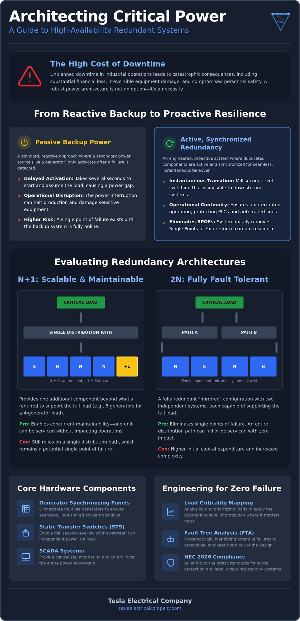
A fundamental distinction exists between passive backup power and active redundant systems. While a standard backup generator might take several seconds to start and assume a load, a synchronized redundant system is often already active or capable of a seamless, automated takeover. This level of redundancy in engineering ensures that the transition between power sources is invisible to sensitive downstream equipment, such as PLC control systems or automated production lines. It moves the facility from a reactive posture to a proactive, high-availability state.
The Cost of Downtime in Industrial Operations
For heavy industry, downtime is a quantifiable disaster. Production halts lead to immediate revenue loss, while sudden power drops can cause irreversible damage to specialized equipment or result in significant safety risks for personnel. Within the UAE national market, regulatory requirements for mission-critical power have become increasingly stringent. Adhering to the NEC 2026 standards is now essential, particularly regarding mandatory surge protection for legally required standby systems and broader arc flash labeling requirements. Redundancy serves as a technical insurance policy, providing a layer of security that guarantees business continuity regardless of external utility conditions or hardware volatility.
Redundancy vs. Reliability: An Engineering Distinction
It’s a common misconception that high-quality, reliable components negate the need for redundancy. While a single component may have a high Mean Time Between Failures (MTBF), it remains a vulnerability if its failure leads to a total system shutdown. Redundant architectures focus on reducing the Mean Time To Repair (MTTR) and ensuring that the overall system availability remains high even when individual parts fail. Engineers utilize the ‘N’ nomenclature to define these levels of protection. ‘N’ represents the base capacity required to support the load, while configurations like N+1 or 2N provide the necessary margin for maintenance and fault tolerance without compromising the facility’s operational output.
Evaluating Redundancy Configurations: N+1 vs. 2N Architectures
Selecting the appropriate topology for critical power redundant systems is a decision that dictates the long-term operational limits of a facility. It requires a precise understanding of the load and the potential impact of a utility or component failure. While many configurations exist, the choice usually centers on the balance between capital expenditure and the required level of fault tolerance. Engineers must weigh the necessity of continuous uptime against the complexity of the underlying electrical distribution.
N+1: The Standard for Industrial Scalability
N+1 redundancy acts as a pragmatic standard for industrial scalability. In this configuration, a system possesses one more component than is necessary to support the full load. If the facility requires four generators to run at peak capacity, an N+1 design utilizes five. This approach enables concurrent maintainability, allowing one unit to be taken offline for service while the others remain active. It’s particularly effective in manufacturing environments where process control is vital. However, it’s important to recognize that N+1 still typically relies on a single distribution path. A failure at the primary bus level will still result in downtime, regardless of how many spare generators are available.
2N and 2N+1: Architecting for Zero-Failure Missions
For environments where even a millisecond of power loss is unacceptable, 2N redundancy is the necessary baseline. This “system-plus-system” approach creates two entirely independent power paths from the utility entrance down to the individual load. Each path is capable of supporting the full facility requirement on its own. When engineers add a spare unit to each of these paths, it becomes a 2N+1 architecture, which is the gold standard for high-stakes infrastructure. This level of complexity requires a sophisticated redundant control system architecture to manage the synchronization and load-sharing between paths.
While the CAPEX for 2N systems is significantly higher due to the duplication of LV and MV switchboards, the investment is often justified by the prevention of a single total-system failure. Large-scale plants may also consider distributed redundancy as a middle ground to optimize costs across multiple load blocks. Finding the right fit requires a partner who understands the nuances of industrial power distribution. You can consult with a specialist to design an expertly engineered redundant system tailored to your facility’s specific criticality requirements.
Core Hardware Components of a Redundant Power Ecosystem
While the architecture provides the blueprint, the physical components of critical power redundant systems determine the actual performance and reliability of the infrastructure. A robust ecosystem relies on high-specification hardware designed to handle the rigorous demands of heavy industry. This includes:
- Low Voltage (LV) and Medium Voltage (MV) Switchboards equipped with redundant busbars to prevent a single bus failure from disabling the entire facility.
- Automatic Transfer Switches (ATS) for standard transitions and Static Transfer Switches (STS) for millisecond-level switching required by sensitive electronic loads.
- A comprehensive Power Quality and Disturbance Recording System to monitor the health of the redundant network and identify transient issues before they escalate into failures.
The integration of these components requires a systematic approach. Each piece of hardware must be rated for the specific fault levels of the plant to ensure safety and longevity. High-quality capacitor banks and VFD control panels also play a supporting role by stabilizing the load and reducing the strain on the redundant power sources during transitions.
The Role of Generator Synchronizing Control Panels
Generator Synchronizing Control Panels serve as the intelligence center for any multi-source power system. These panels manage the complex task of synchronizing multiple generators to a common bus, ensuring precise frequency and voltage matching for stable load sharing. During utility fluctuations, the control panel manages active and reactive power to maintain system equilibrium. Tesla Electrical Company engineers these panels to facilitate seamless utility-to-generator transitions, minimizing the risk of synchronization errors that could lead to equipment damage or system trips. This capability is essential for managing the aggregated risk of low-impact assets as outlined in the latest NERC CIP Roadmaps.
Redundant PLC and SCADA Integration
Resilience must extend beyond the power path into the control layer. Redundant PLC and SCADA integration ensures that if a primary controller fails, a hot-standby unit assumes control without interrupting process monitoring. This dual-layered approach prevents a control failure from triggering an unnecessary power shutdown. Implementing advanced SCADA and automation system solutions allows operators to maintain real-time visibility into the health of all redundant components. By centralizing data from protection relays and circuit breakers, these systems provide the comprehensive oversight necessary for maintaining high-availability environments in the UAE’s demanding industrial sector.
Design and Specification: Engineering for Zero-Failure Environments
Constructing critical power redundant systems involves a rigorous engineering methodology that transcends simple component selection. It requires a granular understanding of how power interacts with the specific industrial process. A successful design follows a methodical four-step progression to ensure the architecture remains resilient under extreme fault conditions.
- Step 1: Load Criticality Mapping. Engineers must categorize every load based on its tolerance for interruption. We identify mission-critical processes that cannot survive a 10ms power drop, such as high-precision CNC machinery or sensitive PLC control loops.
- Step 2: Fault Tree Analysis. This involves a top-down evaluation of the entire electrical grid to expose hidden Single Points of Failure. Even in a redundant setup, shared components like a common neutral bus or a single control power circuit can become a catastrophic SPOF.
- Step 3: Selecting Protection Relays. High-speed fault isolation is vital to maintain the integrity of the redundant path. We specify industry-leading power system protection relays, such as those from SEL or Basler, to ensure any fault is cleared within cycles, preventing it from affecting the healthy side of the system.
- Step 4: Harmonic Mitigation. Redundant paths often supply power to complex electronic drives. Integrating sophisticated industrial VFD control panel design is necessary to manage total harmonic distortion (THD) and protect the longevity of the redundant hardware.
Power Factor Correction and Capacitor Banks
Redundant systems, particularly those in dual-feed or N+1 configurations, require a stable power factor to prevent nuisance tripping of sensitive protection relays. When multiple power sources share a load, managing reactive power becomes increasingly complex. Integrating automatic capacitor banks into the design ensures the power factor remains within optimal limits, reducing the strain on generators and switchgear. This is especially critical in UAE industrial environments where high inductive loads from heavy machinery can fluctuate rapidly. Properly specified capacitor banks provide the necessary reactive compensation to maintain system equilibrium during a transition between power sources.
Specifying Protection and Control Logic
The control logic must be as robust as the physical power path. This requires meticulous coordination of relay settings across all redundant branches to ensure selectivity during a fault. We utilize advanced disturbance recording systems to validate that the system performs exactly as engineered during transient events. Precise coordination of protection relay settings is the fundamental safeguard that prevents a localized fault from cascading through the entire N+1 architecture. To secure your facility’s future, you can consult with our engineering team to develop a custom-specified redundant solution that meets your exact operational requirements.
Modernization: Retrofitting Legacy Systems for Redundancy
The transition toward high-availability infrastructure doesn’t always necessitate a complete facility overhaul. For many industrial operators, the economic case for retrofitting existing assets is far more compelling than a full system replacement. Retrofitting allows for the strategic integration of critical power redundant systems by upgrading the control and protection layers of proven, heavy-duty hardware. This approach significantly reduces capital expenditure while minimizing the lengthy downtime associated with removing and installing new primary switchgear. It’s a pragmatic path to achieving modern resilience without discarding the foundational value of legacy infrastructure.
Upgrading legacy circuit breakers is a vital component of this modernization process. Older units often lack the communication protocols required for sophisticated load-sharing and synchronization logic. By integrating new Generator Synchronizing Panels with existing MV switchgear, engineers can transform a manual backup setup into a fully automated, synchronized power ecosystem. Tesla Electrical Company focuses on industrial system longevity through professional retrofits that bridge the gap between robust mechanical legacy equipment and the high-speed digital requirements of today’s grid standards.
Circuit Breaker and Protection Relay Retrofit
Replacing aging electromechanical relays with modern digital protection is the most effective way to extend the life of existing switchboards. These digital upgrades provide the precision timing and disturbance recording capabilities necessary to support critical power redundant systems. Modern power system protection relays ensure that legacy hardware can communicate seamlessly with new SCADA automation layers, allowing for real-time monitoring and rapid fault isolation. This digital transformation provides operators with the diagnostic data needed to maintain high-availability standards while ensuring that older protection schemes meet the rigorous requirements of the NEC 2026 updates.
Future-Proofing with Scalable Redundant Solutions
A successful modernization strategy must account for future growth. Designing for modularity ensures that additional redundant modules can be integrated as the plant load expands over time. This scalability prevents the facility from outgrowing its power architecture within a few years of an upgrade. Maintaining a comprehensive spare parts inventory is equally essential for ensuring that redundancy uptime isn’t compromised by supply chain volatility or component failure. A well-executed retrofit provides the flexibility to adapt to changing regulatory landscapes and increasing power demands. To begin your facility’s transition, you should Contact Tesla Electrical Company for a comprehensive redundancy audit to identify the most efficient path toward total industrial resilience.
Securing Long-Term Industrial Continuity
Architecting critical power redundant systems is a specialized engineering discipline that requires a methodical approach to synchronization, load sharing, and fault isolation. We’ve explored how selecting the right topology, whether it’s an N+1 or 2N configuration, ensures your facility remains compliant with the latest NEC 2026 standards while eliminating single points of failure. From the precise logic of generator synchronizing control panels to the strategic retrofitting of legacy switchgear, every component must work in harmony to protect high-value assets from unplanned downtime.
Industrial resilience is built on the foundation of technical expertise and high-performance hardware. As UAE national industrial automation experts, we provide the comprehensive oversight necessary to manage complex power requirements from initial design through final execution. Whether you’re building a new zero-failure environment or modernizing existing infrastructure, our team offers full-service retrofit and modernization capabilities to guarantee operational stability. We invite you to Partner with Tesla Electrical Company for High-Availability Power Solutions and secure a dependable future for your mission-critical infrastructure. Your facility’s success starts with engineering excellence.
Frequently Asked Questions
What is the difference between N+1 and 2N redundancy?
The primary difference lies in the level of hardware duplication and fault tolerance. N+1 redundancy adds a single spare component to the base requirement, which allows for maintenance flexibility but often relies on a single distribution path. In contrast, 2N redundancy involves a full duplication of the entire power path. This “system-plus-system” approach ensures that even a catastrophic failure of a primary bus or distribution board doesn’t result in facility downtime.
Do I need a redundant system if I already have a backup generator?
Yes, because a standard backup generator typically requires a start-up period that causes a temporary power interruption. Redundant systems are engineered for active synchronization or millisecond transitions to ensure that mission-critical processes remain active during a utility failure. While a generator provides long-term energy, critical power redundant systems provide the seamless continuity required to protect sensitive industrial electronics and automated production lines from brief outages.
How do generator synchronizing panels improve system redundancy?
Generator synchronizing panels act as the intelligence center by precisely matching the frequency, voltage, and phase angles of multiple power sources. By synchronizing several generators to a common bus, these panels enable active load sharing and prevent damaging surges during transitions. This capability allows multiple units to function as a single, resilient entity. If one generator fails, the remaining synchronized units immediately assume the load without any interruption to the facility.
What are the most common single points of failure in industrial power systems?
Single points of failure (SPOF) are often hidden within auxiliary components rather than primary hardware. Common examples include:
- Shared neutral buses or common grounding points.
- Non-redundant PLC controllers or SCADA communication links.
- Single control power circuits for protection relays.
- Unmonitored capacitor banks that fail to provide reactive compensation during transitions.
Identifying these vulnerabilities requires a methodical fault tree analysis during the design phase.
Can legacy industrial switchboards be retrofitted for redundancy?
Legacy switchboards can be successfully retrofitted by replacing aging electromechanical relays with modern digital protection and upgrading circuit breakers. Tesla Electrical Company specializes in the retrofit of circuit breakers and protection relays to integrate modern redundancy protocols into existing MV and LV infrastructure. This professional modernization extends the lifespan of your switchgear while adding the high-speed communication capabilities required for automated synchronization and remote monitoring via SCADA systems.
How does SCADA integration enhance the reliability of redundant power?
SCADA integration provides real-time visibility and automated control over every component in the power ecosystem. By connecting critical power redundant systems to a centralized SCADA platform, operators can monitor component health and receive early warnings of potential failures. This control layer ensures that redundancy logic is executed precisely during a fault, which reduces the risk of human error and ensures a coordinated response across all redundant paths.
What is the typical transition time for a critical power redundant system?
Transition times depend on the specific switching hardware utilized within the architecture. Standard Automatic Transfer Switches (ATS) typically complete a transition within 50 to 100 milliseconds, which is adequate for most industrial motor loads. However, for sensitive PLC systems and data centers, Static Transfer Switches (STS) are required to achieve transitions under 10 milliseconds. This rapid switching ensures that the power drop is invisible to the most sensitive downstream equipment.
How often should redundant power systems be tested under load?
Redundant systems should undergo a monthly “no-load” test and a comprehensive “full-load” test at least once per year. Regular testing confirms that the synchronization logic and transfer switches function correctly under actual operational stress. Utilizing a Power Quality and Disturbance Recording System during these tests allows engineers to capture transient data. This data is essential for verifying that the system continues to meet its original engineered performance benchmarks.
Disclaimer
Some content, images, text, or other materials on this website may have been created or assisted by artificial intelligence (AI).
While we review AI-generated content for accuracy and quality, we do not guarantee that all information is free from errors or omissions.
Content generated using AI is provided for informational purposes only and should not be solely relied upon without independent verification.
One Response